50.003 - Use Case
Learning Outcomes
By the end of this unit, you should be able to
- Describe the different components of a use case.
- Describe the different components of a use case diagram.
- Analyse the given system requirements using use cases and use case diagrams.
Use case
A use case (or a use case text, or use case document) captures a particular scenario or related scenarios in a user-system interaction to achieve a user goal. Our objective is to find out all relevant user-system interaction in the existing system to be fixed and in the newly proposed system that the users want us to build.
An example - Banking App
Consider the following user interaction with a Banking App
Although in general there is no fixed format of use case text documents, for consistency, we try to adhere to the following convention.
| ID: | UC1 | Name: | Login |
| Description: | Customer Logins to the Bank App | ||
| Created By: | Dileepa Fernando | Date Created: | 1st May 2026 |
| Last Updated By: | Dileepa Fernando | Date Updated: | 3rd May 2026 |
| Actors: | Customer | ||
| Triggers: | Customer opens the Bank app and clicks on login button in the initial screen | ||
| Preconditions: | Customer Not logged in and Bank app installed | ||
| Postconditions: |
1. Customer authenticated and logged in 2. The customer can access the account |
Error States: |
1. Customer not authenticated 2. The customer cannot access the account 3. Login error shown |
| Flow: |
1. Customer enters the password. 2. Customer clicks the login button 3. System validates credentials 4. System shows the dashboard |
||
| ... | |||
In the table above, we define the use case. All non-italic fields are mandatory.
-
For tracking purpose, every use case should be given a unique ID and a informative name. Common convention is to use
<verb>+<noun>format where<verb>implies the goal of the entity initiating the interaction.Loginis an exception which is retained as a<verb>due to clarity. -
The description summarizes the gist of the user-system interaction
-
Though optional (hence in italic), it is also good to keep track of the creator and updater's names and the dates.
-
The actors field includes a set of actors involved in this interaction. In this example, the customer is the primary actor since she is the one who is benefitted mainly. When an actor initiates such a use case, we refer to it as a base use case. The other supporting actors to the base use case are considered secondary actors. Every use case should have at least one actor. We can choose to distinguish between primary and secondary actors.
-
The triggers field describes what activates this use case, which can be a user action or another user case's action.
- The preconditions field includes a list of mandatory criteria/ system state must be met before this user-system interaction is initiated. Sometimes, if a precondition is a common to a set of use cases, we convert it into a common requirement field.
- The postconditions field includes a list of possible output states when the use case completes successfully
- The error states field capture the failed outcomes and optionally a general description of how failed outcomes are handled.
- The flow contains a sequence of actions performed by the actors in chronological order.
Note that there is the ... in the above table, and there is no visible way to trigger the failed postcondition. This is because the use case is incomplete.
Suppose the user requirement continues as follows.
" If the user credentials are invalid system should prompt invalid credentials message "
With this we continue our use case as follows
| ID: | UC1 | Name: | Login |
| Continue from the previous table | |||
| Alternative Flow: | 3'. The customer enters wrong credentials. 6'. System prompts invalid credentials message |
||
In the above, we specify the alternative flow. In the event of either of the alternative-flow actions occur, the error states will be result. In this case, user authentication fails. Main flow is 1,2,3,4,5,6 while alternative flow is 1,2,3',4,5,6'.
Now next consider another paragraph of user requirement.
" The customer selects the Transfer menu from the banking application. The system displays the Transfer Funds screen. The customer enters the recipient’s account number, account details, and the amount to transfer. After confirming the information, the customer clicks the Confirm button. The system prompts the customer to enter a one-time password (OTP). The system sends the OTP via SMS using the SMS Gateway. The customer receives the OTP and enters it into the system. Upon successful verification, the system transfers the specified fund amount to the recipient’s account and reduces the customer’s account balance accordingly. The system displays a success message confirming the transfer.
If the customer initially enters an invalid account number or incorrect details, the system displays an error message. After acknowledging the message, the customer can retry the process by returning to the Transfer Funds screen. "
| ID: | UC2 | Name: | Transfer Funds |
| Description: | Customer transfers money from her account to another account | ||
| Created By: | Dileepa Fernando | Date Created: | 1st May 2026 |
| Last Updated By: | Dileepa Fernando | Date Updated: | 3rd May 2026 |
| Actors: | Customer, SMS Gateway | ||
| Triggers: | The Customer clicks on Transfer menu | ||
| Preconditions: | Customer is logged in and authenticated | ||
| Postconditions: |
1. the customer transfers the mentioned fund value to the selected recipient 2. The customer's balance is reduced by the mentioned fund value |
Error States: | Fund transfer fail |
| Flow: |
1. Customer clicks on transfer menu. 2. System shows transfer screen. 3. Customer enters recipient account number and details. 4. Customer enters the amount to transfer. 5. Customer may choose to add a note 6. Customer clicks on confirm button. 7. System validates the account details and checks the balance 8. System prompts the customer to enter the OTP. 9. System sends the OTP by SMS. 10. Customer enters the OTP. 11. System validates the OTP. 12. System shows the transfer success message. |
||
| Alternative Flow: |
Invalid Account Details: 1-7 (main flow),8.System shows 'Invalid Account Details' message 9. User clicks the message, go to step 2 Insufficient Balance: 1-7 (main flow),8.System shows 'Insufficient Balance' message 9. User clicks the message, go to step 2 Authentication Failed: 1-11 (main flow),12.System shows 'Authentication Failed' message 13. User clicks the message, go to step 8 |
||
In the above use case, we find the Customer as the primary actor, and the SMS gateway as the secondary actor.
Use Case Diagram
Use case diagrams allow us to organize the related use cases into a single diagram. It is like the bird-eye's view.
Now we have two use cases. We can summarize them into the following use case diagram
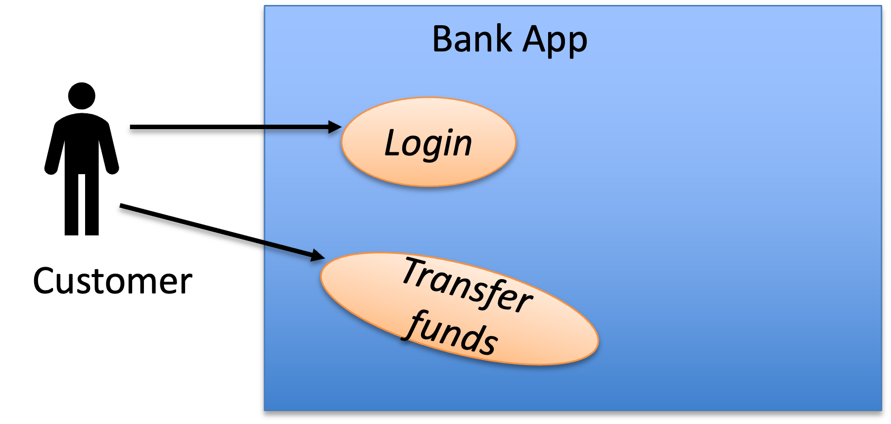 * The rectangle box denotes the system boundary.
* Each stick man denotes an actor.
* Each oval bubble denotes a use case.
* The solid lines denote the association between an actor and a use case. Note that in our notation we do not visually distinguish a primary actor from the secondary actors. We can also infer or clarify using the use case texts. A good practice is to align the primary actors towards left side and secondary actors towards right side.
* The rectangle box denotes the system boundary.
* Each stick man denotes an actor.
* Each oval bubble denotes a use case.
* The solid lines denote the association between an actor and a use case. Note that in our notation we do not visually distinguish a primary actor from the secondary actors. We can also infer or clarify using the use case texts. A good practice is to align the primary actors towards left side and secondary actors towards right side.
Extend Relationship
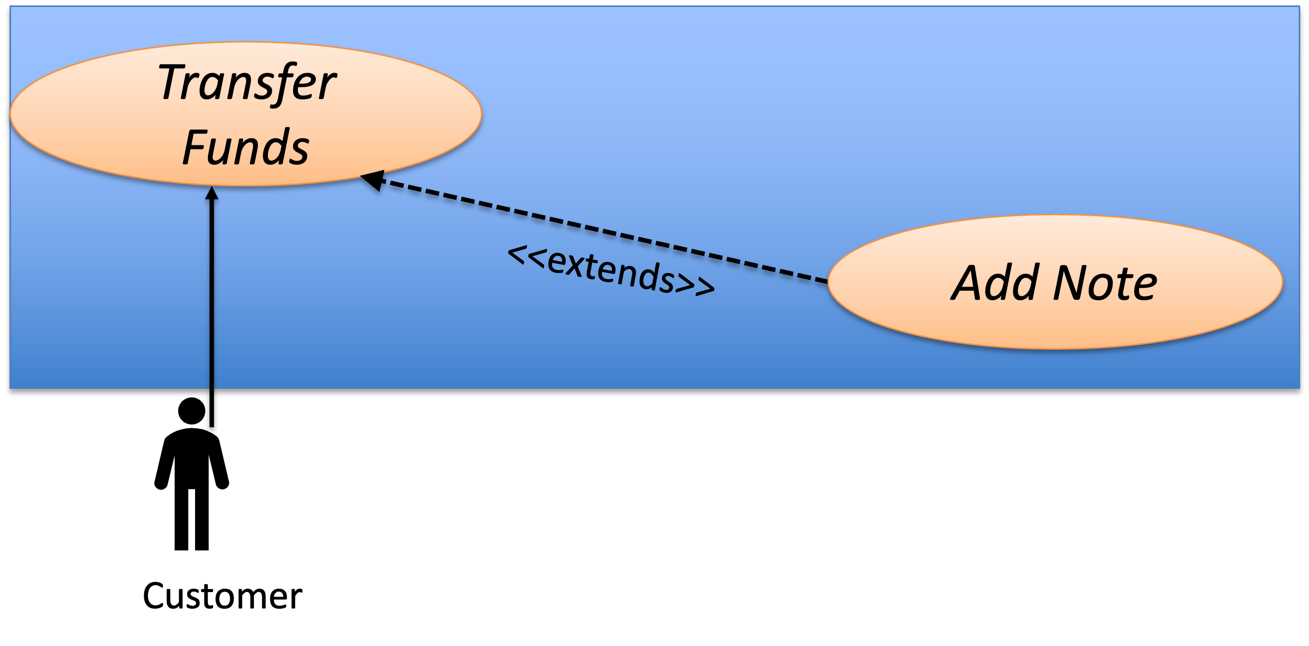
There are scenarios in which we want to include an optional sub use case of the base use case.
When a use case E extends a use case B, E is an optional step in B, in other words, B can be completed with or without E being triggered.
To put it into a concrete example, let's consider a use case text as follows
| ID: | UC3 | Name: | Add Note |
| Description: | The customer adds a note on the fund transfer | ||
| Created By: | Dileepa Fernando | Date Created: | 1st May 2026 |
| Last Updated By: | Dileepa Fernando | Date Updated: | 3rd May 2026 |
| Actors: | Customer | ||
| Triggers: | The customer accesses add note interface | ||
| Preconditions: | The customer is accessing the transfer funds interface and have not confirmed it | ||
| Postconditions: |
Note about the transfer funds is recorded |
Error States: | nil |
| Flow: |
1. The customer enters a note 2. The customer clicks submit 3. The system shows back the transfer funds screen |
||
| Alternative Flow: | nil | ||
We can make UC3 extends to UC1. Note that the extension use case and the base use case should have the same primary actor.
Include Relationship
Sometimes we need to include a mandatory sub use case into another use case so that we can reuse the common routine (it is kind of like a function call).
Suppose the following extension to the project requirements
The system needs to verify that it is the same customer who logged in before proceeding with a senstive transaction such as fund transfer or viewing the bank statement. For this purpose system sends an OTP to the legitimate customer's mobile phone via SMS and prompts customer to enter the OTP. Upon validation, system proceeds to process the sensitive request. Note that UC4 below can be shared among any future usecases which necessitates authentication before proceeding which helps reusability in the use case diagram.
| ID: | UC4 | Name: | Authenticate |
| Description: | The system authenticates customer before a sensitive transaction | ||
| Created By: | Dileepa Fernando | Date Created: | 1st May 2026 |
| Last Updated By: | Dileepa Fernando | Date Updated: | 3rd May 2026 |
| Actors: | Customer | ||
| Triggers: | System prompts the customer to enter the OTP | ||
| Preconditions: | Customer is in progress with transfer fund | ||
| Postconditions: | Customer succesfully authenticated | Error States: | Customer authentication unsuccessful |
| Flow: |
1. System sends the OTP by SMS. 2. Customer enters the OTP. 3. System validates OTP. 4. System shows transaction successful message. |
||
| Alternative Flow: | 4'. System shows authentication failed message 5'. Go to step 1 |
||
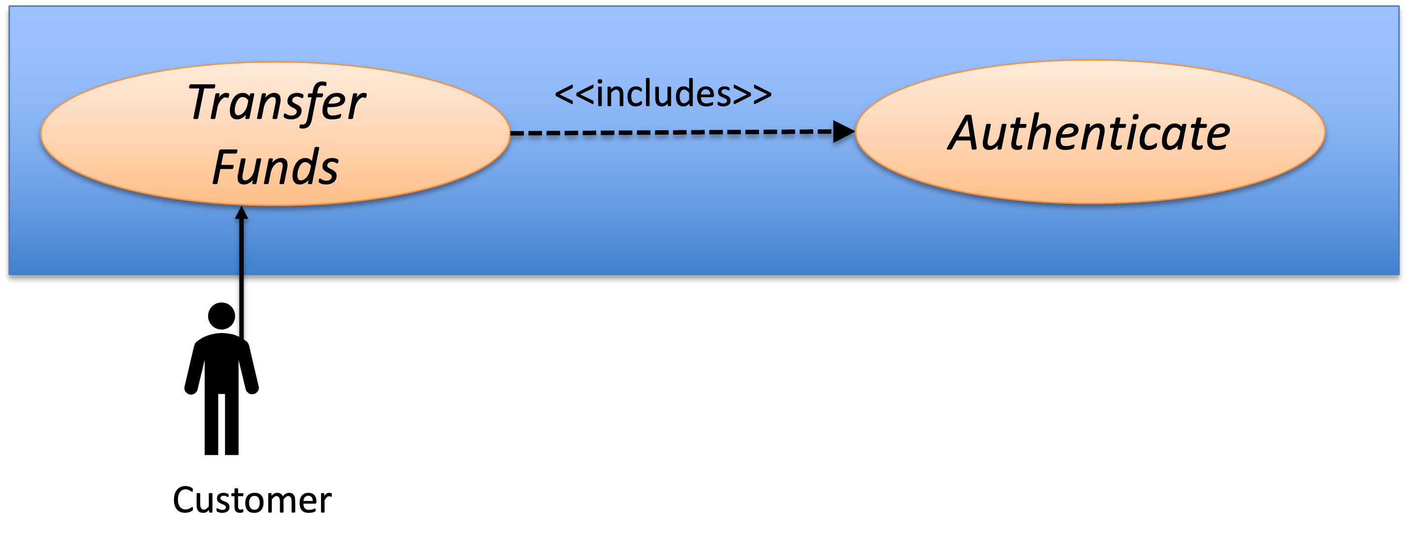
Note that when a use case A includes another use case B, B is a mandatory step in A, A and B must be sharing the same primary actor.
Other relationships
There exist other relationships in use case diagrams.
For instance,
- Inheritance relation among use cases to allow a use case
Ato inherit the base use caseBby sharing the same results with different behaviors. - Inheritance relation among actors to allow multiple actors to share the same base actor's use cases.
We omit the details for these relationships and encourage you to self explore them in the text references.
Deriving Use Case Text and Use Case Diagrams
To derive a use case diagram and its supporting text, we generally gather answers to the following questions through documentation analysis or user studies.
We must first define the system boundary. This separates the system we are building from the outside world, helping us accurately identify who the actors are and what goals belong to our system.
To identify whether a component belongs inside the system boundary, we ask:
- Does our team implement or control this part?
- If this part fails, does a user's primary goal fail?
(Note: If a component is required but not built/controlled by us—like a third-party payment gateway—it sits outside the boundary and is treated as a Secondary Actor).
If the answer is Yes, component is inside the system boundary and component is outside the system (actor) otherwise.
Identifying Actors
An actor is anything outside the system boundary that interacts with it. To identify actors, we need to ask:
- Who are the core users/entities trying to achieve goals using the system?
- Who is responsible for system administration and maintenance?
- Who receives or is interested in the outcome of the system's tasks?
- What external devices or sub-systems must our system communicate with?
The entities which answer the above are considered to be actors.
Defining the Use Cases
Use cases define the functional requirements of the system based on what the actors want to achieve. To define them, ask:
- What are the measurable goals the actor wants to accomplish? (Name these using the standard
<Verb> + <Noun>format). - What specific information does the actor need to read, create, update, or delete?
- Does the actor need to inform the system about changes in the outside world?
- Does the system need to notify the actor about unexpected events or background system processes?
The answers to these four questions directly generate the core components of a formal use case document. The actor's measurable goals provide the use case's <Verb>+<Noun> title and define its successful completion (postconditions). Identifying the specific information the actor needs to read, create, update, or delete dictates the core back-and-forth steps of the main success scenario. Understanding how the actor informs the system about real-world changes establishes the initial triggers and input data needed to start the use case. Finally, discovering how the system handles unexpected events or background processes writes your alternate flows, exception handling, and notification steps, ensuring the use case addresses deviations from the primary "happy path."
Categorizing Actor Types
Given a use case, how do we distinguish the roles of the entities interacting with it?
- Primary Actor: Does the entity have a specific goal they want to achieve, and do they initiate the interaction to achieve it? If so, they are the Primary Actor. (Example: A Customer triggering
Checkout Cart). - Secondary Actor: Does the entity lack a personal goal, but the system relies on it to fulfill the Primary Actor's request? If so, they are a Secondary Actor. (Example: An external Credit Card API that merely responds to the system's request to
Process Payment).
Documenting the Steps
After going through the above questions (often requiring a few iterations), we can map out all the actors, the main use cases (the oval bubbles), and their relationships.
For each individual use case, we then write the Use Case Text. This details the exact sequence of back-and-forth interactions between the actor and the system required to achieve the goal.
A Note on Quality: A use case is a tool for communication, not a mathematical statement. Its quality is determined by how effectively it conveys the user's need to developers, designers, and stakeholders.
For instance, in our running example, we could have combined
UC1andUC2into one larger use case. However, keeping them separate currently helps us describe the system requirements more clearly. At least, I find it easier to explain how use cases work this way! =)
Advanced Tip: Avoiding UI Details in Use Case Text
When writing the step-by-step sequence of a Use Case, be careful not to trap yourself in specific UI implementations. Use Cases should describe the *intention*, not the interface. * **Weak (Too technical):** "The user clicks the blue 'Submit' button, and the system queries the SQL database." * **Strong (Goal-oriented):** "The user submits their login credentials. The system validates the credentials." By keeping the steps focused on the flow of information, the Use Case remains valid even if your team completely redesigns the user interface or swaps out the database.(Optional) Use case vs User story
User story (AKA feature) is another form of capturing the user requirements. It is often used in combination with iterative style development processes.
Contrasting with use case, user stories are more specific to system functionality rather than the user-system interation. Use cases are more "narrative" than user stories and providing a bigger picture. User stories are often more fine-grain than use cases and are helpful for us to divide the development tasks.
We can use both when approriate, for instance, we could start with use cases, then we break down the use cases into smaller user stories. Another way could be starting with user stories, then we can reconstruct the use cases by organizing all the user stories created.
Summary
In this we studied use case texts and use case diagrams and how to apply them to describe the system requirements.